Tuesday, February 08, 2005

The Sound

My T12 is into 10 hours of burnin and the sound is much better. The high and low extension is very more extreme, the base are tight with good control and the sound stage is very realistic and pin point accurate. It is also a very fast amp, listerning to large orchestreal piece does not show any trace of looseness. Overall, I am extremely happy with its performance!

Saturday, February 05, 2005

Testing

All voltages are very close to what specified on the book. But each time I switched on the amp, the bias takes about 15 minutes to settle to the 0 value. Initiall, I it takes awhile to burn that it to make it more stable. But after asking in Transcendent forum, Bruce told me that there is a tube that is marginal. I can sort of pick the tube as it glows much more than the others. After changing this tube, everything is back to normal. Settles pretty much at the start.

Initial impression of the sound is very very good! I have heard this amp in my friend's home, but when I hear my own creation in myown house. This is really touching. The extension to both ends are very good at the start already The control of the base is very good and the amp is extremely fast. There are a lot more datails I can hear now that just wasn't audible before.

Now I am burning it in with the STS Burn-in CD with the speaker terminal connected to a 100W 10R resistor. Hopefully, this will speed up the burn in process without causing complaints from my neighbours.

The amp is running quite hot though, I measured the top cover of my amp and it is recorded 60deg!


I would like to thanks Bruce for creating such a wonderful amp and made this available to all of us!

Circuit modification

I have made some modifications to the circuit shown in Audio Reality based on my friend's comment.

1. C5 & C6 is now combined to 22uF 630V Solen
2. All voltage doubler were changed to full bridge
3. All electrolytic ripple rejection caps on the 550V and negative bias were changed to solen MKP
4. All Caps on the +/- 170V were parallel with 0.1uF MKP
5. The bias circuit was also changed to cater for my need. I found that using the original values, I could get the bias no matter how hard i swab the tubes. I remember I read somewhere that the current in the bias section is 4ma, I measured the voltage after the full bridge is -305V. I works out that I need 20K for the R50 & R51, 38K for R52 & R53 and 10K for R54 to get the values of -40V and -200 - -220V. After I changed the values, the bias is OK.
6. All small valve (Au7 and Ax7) are arranged in parallel with a regulated voltage for filameents. The regulating circuit is simple LM1085 circuit
7. CL1 was changed to CL60 to cater for 220V
8. Tubes have a lot of problems. the so called EL509 is not really EL509. See here I used EL519 instead

Sunday, January 16, 2005

The case

Now, I still need to settle on the chassis. I actually have it tailor made in a local store according to my size, spec and the holes drilled. I then put them together with aluminium rods which I bought in material store.


Making the case is actually the hardest part and I need to satisfy my wife as well.... In oder to make it look nice, I have decided to add piece of sand stone as the face cover, under the sandstone is a layer of transparent PVC so that the blue LED will shine trhough


To allow the tubes to breath, there are many holes which will eventually covered with metal gauze


Mechanical damping

Some people say that the smallt tube will amplify mechanical vibrations as well. This is the so call microphone effect. While this is not usually a problem for the AU7 and AX7, I have made some adjustment to the case design so taht the tubes are suspended from a rubber sheet.


The circuitry

Being the first time to wire point to point, I paid particular attention to all the details and luckily, with all the help from many many net friends, I was able to get it done.


Ripples reduction

To reduce the ripples, a large number of capacitors were used. In fact, a large proportion of the cost goes to capacitors,

For the 2200uF, I used RIFA with added choke to make it low noise. For the other 22uF, I used Solen, In general, the MKP is faster than electorlytics. So inorder to compensate for the slowness of the RIFA, I also parallel each of them with a 0.1uF UCC SPP capacitors.

At the final output I also parallel each rail with a 1 ohm resistor in series with a 0.1uF UCC SPP cap for reducing the inductance. For reference see here


The grounding of the +/- 170 rail is also carefully arranged with red copper sheets


you may noticed that the screws are very shiny..... yes they are silver plated... order last time from Fay Hing. Isn't group order nice!

Power supply unit 2

So there goes the power supply unit. When I built my GG, i had a lot of problems with noise. So in the design of my T12, I pay particular attention to the isolation, the case deisgn is devided into 4 layers, the bottom layer is where the transformers are placed. this mainly contains AC.

Right above it is a layer of bridge, regulators and all conversion to DC is done on this layer.


Then comes the capacitor layer where all the ripples are removed


the layers are also separated with copper sheets which are know to minimize RFI

Power supply unit

There are a few power supply units required for T8:

the transformer that provide the 550V, it is specified to be a 200V, 100ma transformer, however you would expect a significant voltage drop and I chose a 430V, 40VA transformer and planning to use full bridge rather than voltage doubler. This spec gave me 520 at the end....

The negative bias supply reuired a 120V, 10VA transformer. I combined the two and order a 50VA transformer from LITE

Different from the original circuit, I also use a separate transformer for the AU7 and AX7 filaments. I use a 50VA transformer for a LT1085 regulated power supply. Some people believe using AC for filament can give a bit more dynamic but I am not sure if that's really dynamic of variability that one is hearing. From science point of view, using regulated DC can reduce noise and so used DC.

In order to protect the EL519, I also created a delay circuit to control 2 relays so that the +/- 170V is connected only after 40s and when the filaments of the EL519 are growing....

All these are placed on one single PCB


Calculating the OTL power

Well well well, a bit of maths here!

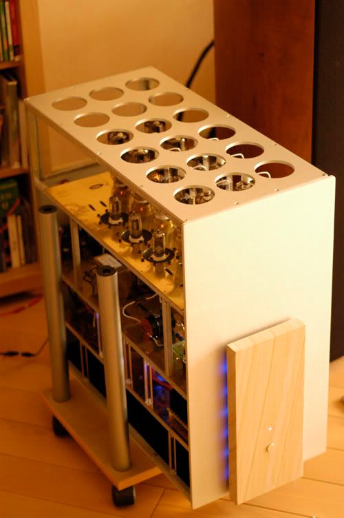
On the Transcendent forum, I asked a bit about the calculation of OTL power and I wonder what sort of power will my T12 OTL output?

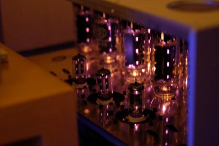
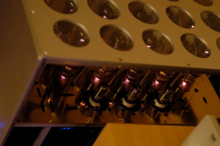
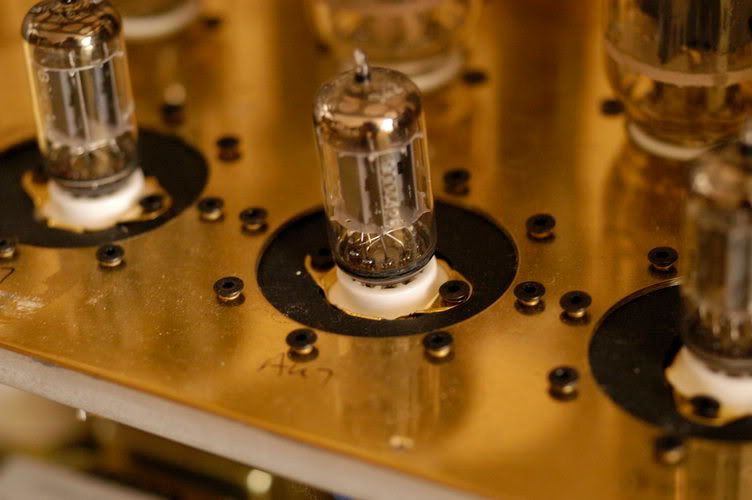
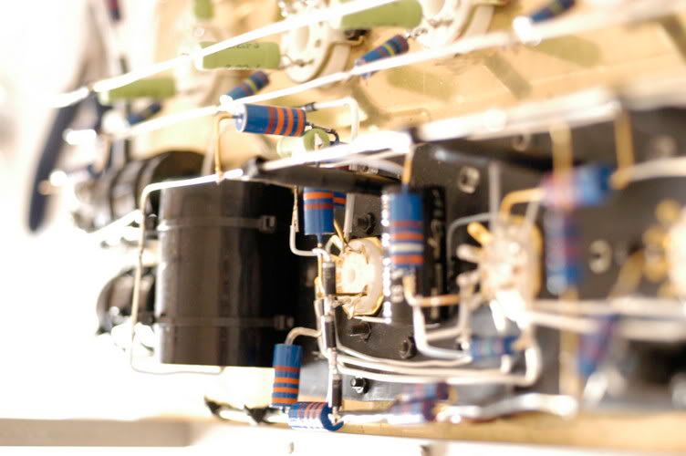
Well, each tube of EL519 can generate about 1A and there will be 6 in each bank giving about 6A in AB mode as the peak current.

Solving the equation Ipeak = 6A = sqrt(2*power/speaker resistance)
Assuming the speaker resistance is 8ohms,
power of my T12 = 144W.

Well, not bad!

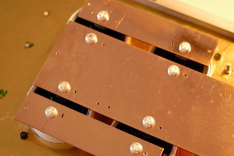
But that also put extra demand ont the transformers
6A peak current is about 4.3A RMS, operating at 50% duty cycle, requires a transformer with about a 2.15A secondary.

So the transfomer I need would be 135V x 2 x 2.15 = 580VA
Oops, I only have a 450VA transformer.......

What can I do? Well another phone call to my tutor Tai Po and he suggested to use 2 transformer in parallel. Well not perfect, and some people hate this..... but unless I buy another high VA transformer, I am running out of option....

Transformers

the transformers for the +/- 170V and the filaments for EL509/EL519 are from a very nice net friend momo. It was originally from 梁氏. However, they are a bit over spec and the voltage are +/- 135V without loading and 23V for the filaments. This prompted me to work on the idea of 12 tubes....

However, the transformer is of very good qualities. I did plan of showing the transformer outside the case but worried about if it is not a good one and need to be replaced......

Saturday, January 15, 2005

Preparation

No, it isn't a commercial one but a scratch build one.................

The preparation for T8 components take about 4 months..... The search for the best parts available has taken its toll.....

Transformers, choke, RMGs, Kiwawi resistors, SCR caps, MCaps, Silver wires came from all over the world waiting to be put into one box. Well, 2 boxes really. When the transformers came, I couldn't wait but test the voltage output..... oh no 135V without loading..... That makes it >190V after bridge!

What am I going to do?

A few messages with Tai Po solve the problem..... changing the bias circuit......
Well, being a very anal retentive person, I am not happy..... The voltage for the filaments for EL519s are also too high!!! Then another thought strike me...... How about using 12 tubes and make a T12?........

A journey with T8

It all started one year ago when I completed my first DIY - the GG. It took me 1 month to complete the project but the satisfaction on each step of the project was great let alone the great sound I get at the end of it!

But most important of all, during this project, I met many great GG builders like Tai Po and Tam Sir and to allow my fever to a new height, I have decided to move on ...... T8 mono....